

The T4 has been one of our most important and also most successful projects. Over the years there has been continuous development, and in the last 20 years we brought out a new & improved car every year. Development has been, in many cases, the result of external factors such as the change from brushed to brushless motors; change of batteries to LiPo packs; new super-lightweight electronics; and new materials and technologies which allowed us to come up with creative new ideas that were not possible before.


The other part of development has been our never-ending desire to make the car faster and easier to drive while still gaining more steering and stability.


And then of course you have the competition that always pushes you to reach new levels. The competition in this class has been always very high and pushing us to do better, but to be honest it was mainly the competition that pushed all boundaries and forced us to work harder, smarter, and faster while still being more precise and keeping our focus on the smallest details.


In high-competition racing, in the end it is always about those small details… and sometimes about luck. In the last decades we have won hundreds of National titles around the world, dozens of US National titles, and plenty of Asian and European Champion titles… but we still did not win the World Champion title. Despite being very very close so many times, many times we were missing that one small piece: a bit of the good luck. But we never gave up and after almost 20 years of dedication, passion, and patience we won the Worlds!


We have said it before, and we will say it again: development is never ending! So we are very proud to present to you a glimpse of our all-new T4 platform, the completely redesigned 2020 T4. Our R&D department and Racing Team has spent nearly a year to completely change and improve the T4. This is not a minor “facelift,” this is a completely redesigned platform that boosts the performance of the car to an entirely new level, believe me.


As usual, external changes were one of the main forces that pushed development further. In the last year in many racing series and countries there were changes that had a significant influence on the car.


- Body – Some race series do not allow the use of lightweight bodies. The heavier “standard” bodies decrease steering a lot, and we needed to adjust the performance for both lightweight and standard bodies. Recently there was a big boom of downforce bodies which improved traction and stability, however they completely changed the handling of the cars.
- Additives – Some new tire additives which are subscribed at many race series have more oil, and as such give different driving characteristics.
- Tires – Tire manufacturers improved the reliability and lifespan of their tires by using harder compounds which also helped with traction rolling, but at the same time decreased the overall traction of the cars.


All of those recent changes presented all-new challenges for car designers and put us back to our drawing boards.
Are you excited? Do you want to know more?
My name is Martin Hudy and I am the Chief Designer of the T4 platform at XRAY. I will be exclusively revealing some exciting details about the development of our latest T4. Read the exclusive story below.


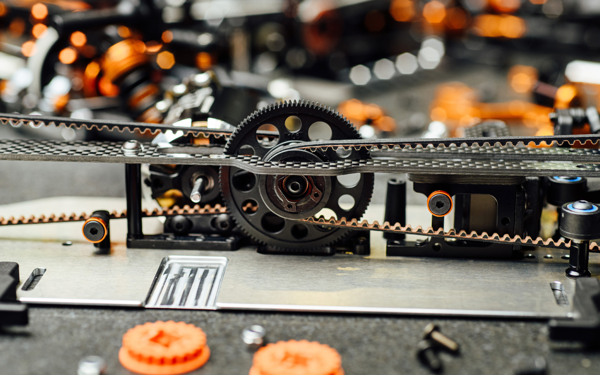
Layshaft and Motor Mount
The most important, key change on the T4 platform is the placement of the layshaft.
Initially I designed a new 1-piece motor mount with the layshaft in the middle of the car and with the motor placed behind the layshaft.
This design allowed the use of same-length belts in front and rear, which improves the weight balance and on/off power feeling of the car.


To make back-to-back comparison tests, I designed a new chassis which allowed easy changes between 3 different layshaft-position alternatives:
1.) Motor mount and layshaft bulkhead separated from each other, like on the current car
2.) 1-piece rearward motor mount, mounted in the chassis centerline
3.) 1-piece frontward motor mount, also mounted in the chassis centerline

It was important to keep the same belt orientation in all the different alternatives, as I wanted to keep the servo mounts in the center of the chassis.
To make proper test comparisons, I also had to make separate prototypes for the aluminum chassis.


During several months of development, I made and tested around 10 different motor mount designs – some of which also required different chassis designs – so we were constantly on the track.


Extensive tests with the alu chassis were done at our in-house indoor carpet track, and tests with the graphite chassis were done at our outdoor asphalt track in low-traction conditions.
Already with our starting set-up we found that the layshaft in the middle of the car gave more stability and generates more traction, which was exactly what we were looking for.


Once I had a clear idea on the position of the motor, I finished all the details on the layshaft design and focused on making the layshaft and the holders ultra-narrow to keep the batteries as close to the chassis centerline as possible. That would result in less chassis roll, proper weight transfer, and a much easier car to drive.


Suspension Arms
To increase the stability of the car I wanted to try longer suspension arms. Not a bit longer… significantly longer!


Many years ago we used to have long arms on our very first T1 platform, but back in this time the cars were not as fast as today and to make the car reactive we had to change for shorter suspension arms. However, with today’s fast cars the longer arms could bring back the desired traction.


But before making any changes to the moulds I wanted to be sure that our theory will work.
We made the first prototypes with longer arms from aluminum, and compared them with our current short aluminum suspension arms.


It was great relief when the first tests proved our theories correct. I felt the car had more traction, more stability, and it was easier to drive in chicanes as the car stays more flat.
Once I knew that longer arms had real potential, we decided to work on the moulds.


The first step was to make the arms without any holes so we could easily drill different shock mounting positions. And also make different lengths to compare the characteristics under different track conditions.


I do not remember the exact number of different alternatives we made and tested, but it was probably close to 20 different designs.


The current design of the ULP shocks works great and I did not want to make any changes to them directly. However, I still wanted to test even lower shock mounting positions to lower the center of gravity.


The quick solution was to make different shock extensions. As I expected, the lower shock mounting positions made the car more stable especially on carpet tracks.


This positive outcome convinced me to change the design of the final suspension arms to include two different mounting positions.


With the all-new suspension design I wanted to fully integrate the ARS system so there was no need to change the suspension arm holders when you want to switch between standard and ARS suspension.


After some creative engineering and design, I came up with the final design of the arms where I combined both types of suspensions into one.
Easy and smart.


Bulkheads
Because I moved the arm mounting positions more to the chassis centerline, I had to modify the bulkhead design


There were three different bulkhead prototype stages:
1.) The first prototypes were quickly modified from the previous design where we simply removed the material in the lower part to avoid the suspension arm collisions.


2.) For the second prototype, we milled 1mm groove in all the bulkheads and upper clamps so we could move them more to the chassis centerline but still use our standard, well-proven differential.
With all the modifications made on the bulkheads, I was finally satisfied with the performance. It was time to finalize the design.


3.) The third and final prototype design brought the most significant changes. I improved all the weak areas and significantly reduced the CG. How? We moved the anti-roll bar below the drive shafts and made the holder super tiny & lightweight.


There was a small dilemma about what to do with the shock tower centering pins on the upper clamps.
I really liked the shock tower centering pins as I did not have to reset the ride height or check the tweak after the shock tower disassembly. But the test results showed that the car generates a bit more traction without the centering pins


So in the end when it comes to the performance, I took a “no compromise” approach - the final design has no centering pins.


Chassis
The chassis is one of the most important parts for the flex of the car, so logically we spent a lot of time on it and designed plenty of alternatives. How many? I guess it was at least 15 different designs.


The first step was to make one chassis to test and compare all three different motor mount systems: motor rearward, motor frontward, and standard motor mount with split layshaft bulkheads.


Extensive tests proved no difference in performance between the split layshaft bulkheads and the new rearward motor mount position. So from that point I focused only on the 1-piece motor mount in both frontward and rearward alternatives.


The plan was to design a universal chassis where the driver only had to change the motor mount, belts, and top deck to easily swap between those two different configurations.


In order to have both frontward and rearward motor mount alternatives, we had to mill two pockets on each side of the chassis.


Unfortunately, the chassis with 4 milled pockets already had too much flex so suddenly the car was more difficult to drive. This was not the way to go.
To solve that flex issue, I tried to remove 2 pockets on the battery side but this resulted in uneven flex.


So unfortunately I had to give up the idea of one universal chassis so there will be only one motor mount position on the final chassis.


After testing a few more alternatives, we came up with a final design for the graphite and aluminum chassis.


The last challenge was to design the flex version of the aluminum chassis for medium and low-traction carpet tracks.


I prepared 6 different alternatives with different flex cut-outs and tested them all in one day under the same traction conditions.


Even after the final design was chosen, I was still thinking of how we could possibly mount the shorter suspension arms for some specific, super-tight technical tracks.
As a solution I added other mounting positions that will allow you to install suspension holders for shorter arms.
Designing the proper shape of the touring top deck is an alchemy. On our previous platform we spent years


Top Deck
Designing the proper shape of the touring top deck is an alchemy. On our previous platform we spent years
to fine tune our top deck shape. With the all-new chassis with the frontward motor, we were again at the starting point zero.


At the start I designed several different alternatives which we tested back-to-back both on carpet and asphalt.


One top deck had less material in front, another had less material in the rear, and the other one had a stiffer middle area. To give us a range of choices, I made all these different designs in 4 different thickness alternatives.


My first goal was to make the top deck symmetrical like the chassis. This was a real challenge as until now there was no other car with the middle layshaft position with a symmetrical top deck.


My second goal was to design one universal shape to cover all different traction conditions. Some drivers preferred the top deck with more flex in the rear, while others prefer a stiffer design. I had the feeling there could be a setting in between.
After extensive work, we made the top deck perfectly symmetrical but also with the all-new unique set-up feature that allows 3 different flex settings.


How does it work? It is super easy, yet very effective.
The top deck works together with a connecting stand.
1.) Soft setting – The top deck is not connected to the stand which gives maximum flex and the car generates maximum steering but it is a bit more difficult to drive.
2.) Medium setting – The top deck is connected to the stand through a ball-bearing which allows the top deck to flex side-to-side but not front-to-rear.
3.) Stiff setting – The top deck is connected to the stand through a fixed bushing that completely stiffens the whole car and makes it very stable.

This all-new unique flex setting is something that all the drivers will enjoy and appreciate and I am proud that even small details like this, make a huge difference in handling and performance and is something that defines XRAY that makes us to keep motivated to push the boundaries further.


I hope you have enjoyed my short story about the daily tasks and work of an RC car designer. All these details shared with you is just a small fraction of all the duties and challenging work we and our R&D and racing team are going through daily to ensure we bring you at the end the best performing and most reliable cars. My name is Martin Hudy, the chief designer of XRAY and I am proud to present you our all-new T4 platform. Enjoy and have fun.